Passive Fiber Optic Components and Modules Manufacturer
Our designs have been qualified and deployed in space applications and are widely used in terrestrial and submarine telecommunications systems.
- Home
- Application
- OTDR
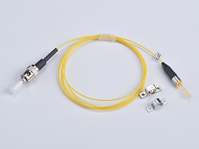
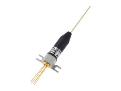
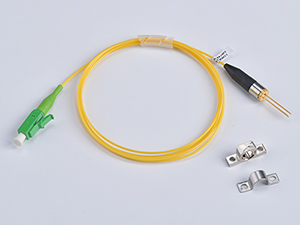
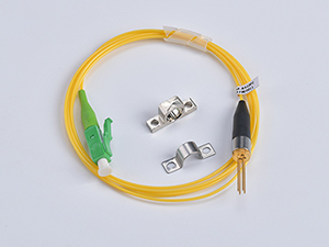
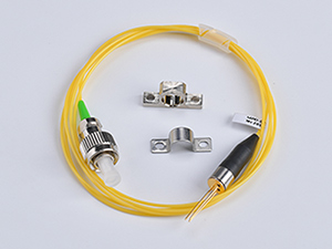
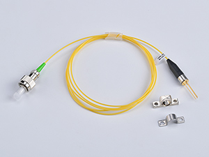
- 1310nm Pulse Laser for OTDR
1310nm Pulse Laser for OTDR
Features
- High output power Pf = 20~50 mW @ IFP = 200mA
- Long wavelength λC = 1310 nm
- Built-in/out monitor PD
- Pulse Conditions: Pulse width (PW) = 10 μs, Duty = 1%
Applications
OTDR System
Absolute Maximum Ratings
| Parameter | Symbol | Min. | Typ. | Max. | Unit |
| Pulsed Forward Current | IFP | - | - | 500 | mA |
| Reverse Voltage | VR | - | - | 2 | V |
| Reverse Voltage (monitor PD) | VRM | - | - | 10 | V |
| Reverse Current (monitor PD) | IFPM | - | - | 2 | mA |
| Operating Case Temperature | TC | 0 | - | 60 | ℃ |
| Storage Temperature | Tstg | -40 | - | 85 | ℃ |
| Lead Soldering Temperature | Tsld | - | - | 260(10s) | ℃ |
| Relative Humidity (noncondensing) | RH | - | - | 85 | % |
Optical & Electrical Characteristics
| Parameter | Symbol | Min. | Typ. | Max. | Unit | Notes |
| Forward Voltage | VFP | - | 2.0 | 2.5 | V | IFP = 200 mA, PW = 10 μs, Duty = 1% |
| Threshold Current | Ith | - | 20 | 35 | mA | - |
| Optical Output Power From SM Fiber | Pf | 20 | - | 50 | mW | IFP =200 mA, PW = 10 μs, Duty = 1% |
| Center Wavelength | λc | 1290 | 1310 | 1330 | nm | IFP = 200 mA, PW = 10 μs, Duty = 1% |
| Spectral Width | σ | - | - | 4 | nm | RMS (−3 dB) |
| Rise Time | tr | - | 0.5 | 1.0 | ns | 20-80% |
| Fall Time | tf | - | 0.5 | 1.0 | ns | 80-20% |
| Monitor Current | Im | 0.05 | - | 2 | mA | VRM = 5 V |
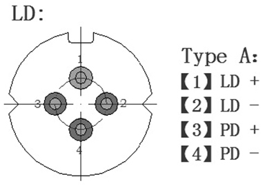
Pin Description
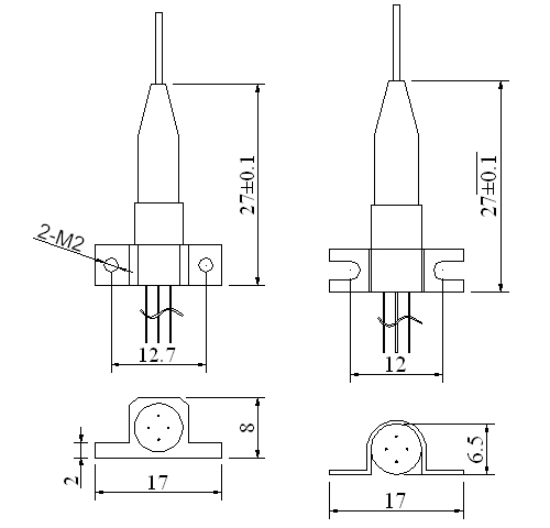
Package Outline
Inquiry Form

